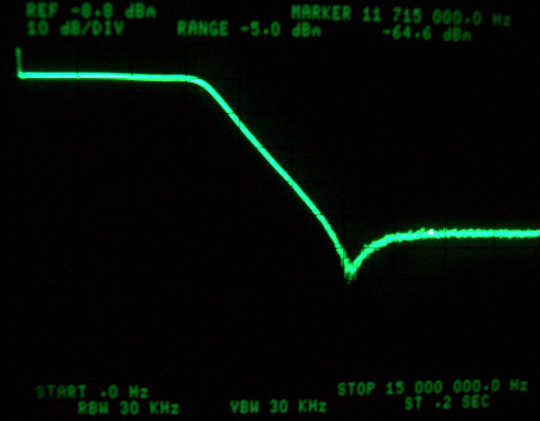
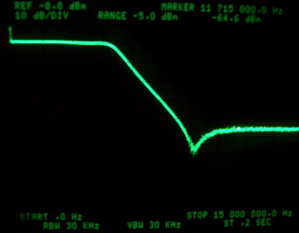
VIDEO LOW PASS FILTER DESIGN TABLE
By: Don McClatchie
Video low pass filters are useful to reduce noise for analog video signals and as anti-aliasing for analog to digital equipment designs. When used in analog noise reduction designs the cut-off frequency is set just above the highest useful frequency in the program content. The same is true for analog to digital systems when used as an anti-aliasing filter. This table will give you an easy way to build a video low pass filter and you will be able to see the relationship between the capacitor and inductor values.
The table below shows input and output resistance values for the Rs, Cs, and Ls. This table has component data for 5th order (5 active element) filters with a 1dB in band ripple. Use inductors with a high Q or (low internal resistance) for maximum rejection of out of band signals.
When using a video generator, the R1 resistor is not used and should be Zero because it is built into the generator output impedance. Also, the termination resistance R2 is also not used when the signal is used with a monitor or other video test equipment that has an internal or external 75 Ohm impedance. This table is used for video projects so the input and output impedance is 75 Ohms at all frequencies. As long as the input and output impedance is 75 Ohms you can use this table for any RF project filter.
If you are using standard non-video test equipment, be aware that the output and input impedance is likely to be 50 Ohms and a 50 Ohm to 75 Ohm impedance match should be used.
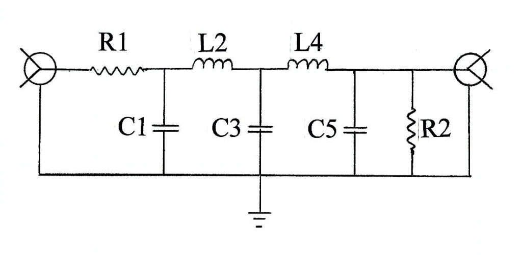
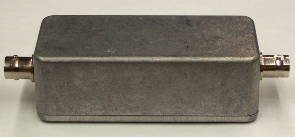
Use the table below to fill in the values for the schematic above. R1 and R2 are both 75 Ohms or zero if the test equipment has the source and termination resistance build in. You can mount this circuit in a metal box with two BNC video connectors and have a handy inline filter to limit the bandwidth of any video signal to remove interference caused by out of band noise or signals.
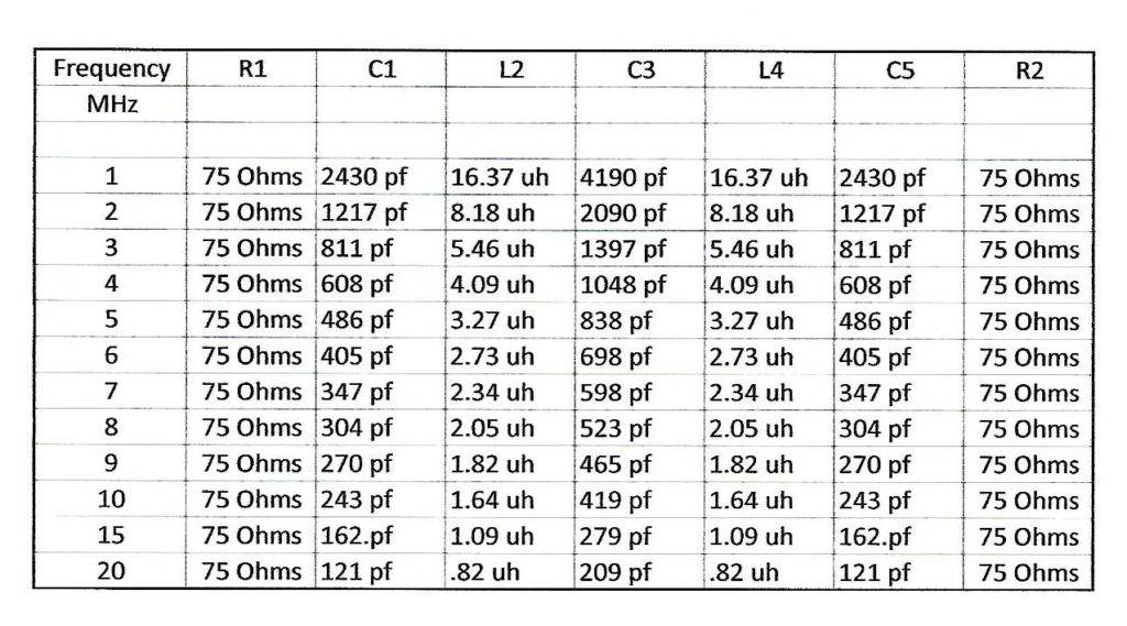
pf = Pico Farad
uh = Micro Henry


