Description
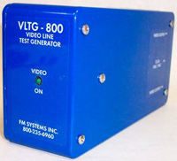
VLTG-800


Part Number: VLTG-800
Title: VIDEO LINE TEST GENERATOR
Category: Test Equipment
Industry: CCTV/Security
Description:
The VLTG-800 Video Line Test Generator creates a standard NTSC video signal that can be observed on a Monitor to display a series of vertical lines that defines the maximum number of “lines of definition” that the CCTV system is capable of displaying. The Generator creates eight groups of lines, ranging from 100 to 800 lines. By observing which groups of lines are crisp and clear and which groups are blurred and indistinguishable, the maximum number of “Lines Of Definition” may be easily determined. The VLTG-800 test generator can be used to establish overall CCTV system quality level as well as to identify components or sections of the system that do not meet system objectives. When the VLTG-800 is used together with the CM-1 Camera Master a very accurate system alignment can be obtained using Equalizer / Amplifier Senders and Receivers to flatten the frequency response of the coaxial cable or twisted pair wires connecting the camera to the monitor location. The CM-1 Camera Master can measure both the low and high frequency loss of the transmission facility. The Sync Pulse amplitude measures the low frequencies while the Color Burst measures the high frequencies. The LEVEL control of the Equalizer/Amplifier is used to set the Sync Pulse to 40 I.R.E. Units while the Sharpness control of the Equalizer/Amplifier is used to set the Color Burst to 40 I.R.E. Units. When both controls are set to 40/40 Units the system is equalized to the best possible picture transmission quality. The ability of a Monitor to display fine picture detail can be measured by connecting the VLTG-800 directly to a terminated Monitor while observing the highest number of lines that are clearly observable. This will establish the finest detail that a particular Monitor can display. A higher quality Monitor must be employed if higher picture quality is required VLTG-800 VIDEO LINE TEST GENERATOR The ability of a Recorder to reproduce picture detail can be measured by recording the VLTG-800 signal and playing it back into the Monitor while noting any loss of “lines” compared to direct connections to the Monitor. In overall system tests, any part of the system may be “swapped-out” or by-passed to identify degraded or defective components. When the CCTV system has been equalized to the best possible transmission, the highest number of “lines of definition” measured at the Monitor will also indicate the highest number of “lines of definition” that any camera can deliver to the Monitor. A Camera with higher “lines of definition” will not improve the picture quality if the Monitor cannot reproduce the increased “lines of definition”.By measuring the capability of each part of the CCTV system you can properly match the equipment to produce the highest Picture Definition for your money. When a customer asks for improved picture quality on an existing system, you can determine which part of the system is limiting the picture definition and replace only that equipment. OUTPUT SPECIFICATION Video Format NTSC / CCTV B/W and Color Output Impedance 75 Ohm Sync Level 40 I.R.E. +/- 0.5 I.R.E. Unit Luminance Level 100 I.R.E. +/- 0.5 I.R.E. Unit Color Burst Level 40 I.R.E. +/- 0.5 I.R.E. Unit Video Pattern 100 – 800 Vertical Lines Pattern Steps 100 Line Increments Video Connectors 2 BNC Female (Dual Output) MECHANICAL Power Requirement 12 – 24 Volts DC/AC Current 55 mA (@ 24 VDC) Power Supply 24 VDC Power Cube (supplied) or Existing Camera Power Size 6.5″ X 3.25″ X 2″ Enclosure Die-cast Aluminum POWER SUPPLY AND ACCESSORIES INCLUDED


