Description
ALARM RECEIVING UNIT


Part Number: ARU478
Title: ALARM RECEIVING UNIT
Category: CCTV
Industry: CCTV/Security, TV/Radio Broadcast, CATV Cable Industry
Description:
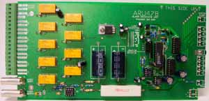
ATU-8 / ARU-478 ALARM RECEIVING UNIT These devices receive alarm and control signals encoded on video in coaxial cable, twisted pair wire, fiber optic and wireless applications. You can insert your alarm and control signals anywhere a video signal is being used for CCTV or Broadcast TV. Alarm and control signals may be carried over any distance by the video signal. The unit provides video when no video is present to maintain alarm continuity. The ATU-8 ALARM TRANSMITTING UNIT and the ARU-478 ALARM RECEIVING UNIT together make up an 8 channel alarm and control Superhighway which can provide up to 160 alarm and control channels on any one video signal. The alarm and control signals are inserted into the Vertical Interval of the video signal so that they will not interfere with the picture. When the video signal is recorded, the alarm and control information is also recorded and can be recalled at play-back. Alarm and control signals will be correlated with the video events. Each pair of ATU-8 / ARU-478 will transmit 8 alarms. Twenty sets of units may be connected to any one video channel, allowing 160 alarms to be transmitted on one coaxial cable. The operating channel can be set by the user in the field with the internal program jumper jacks. A system alarm will operate upon loss of power to either terminal or loss of transmission path (cable cut). In the event of power failure the video through-put is not interrupted. An internal video sync generator takes over and maintains continuous alarm system operation in the event of video signal failure. Contact closures to the ATU-8 input will be repeated as contact closures at the ARU-478 output. The ATU-8 is housed in black ABS enclosure that has a UL flame rating of 94-VO and is powered by a 24VAC power supply. The system has provisions for battery back-up and LED power indicator lights to help installation. The ARU-478 is a card that fits into the RMS400 Mainframe. Nine ARU-478’s will slide into one RMS400 Mainframe. The RMS400 Mainframe is three standard Rack Units high (3 RU) and 19″ wide. It is equipped with dual redundant power sources and will hold any mix of FM SYSTEMS, INC. 400 series products. ATU-8 ALARM TRANSMITTING UNIT ALARM INPUT SPECIFICATIONS Channels 8 Connector 20 Pos. Screw Terminal Alarm Sense Contact closure (Loop) Maximum Loop Resistance 1K Ohm (Specify if Supervised) VIDEO INPUT / OUTPUT Standard NTSC (Color or B/W) No Video Internal Video Generator Impedance Hi-Z Video loop through Connectors 2 BNC (female) Standard Video-On Indicator L.E.D.IndicatorFlasher Internal Video Generator Automatic on Video Loss MECHANICAL Size 5.50″L X 4.3″W X 3.0″D Power 24 VAC 325 mA Battery 24 VDC Not Included ARU-478 ALARM RECEIVING UNIT ALARM OUTPUT SPECIFICATION Channels 8 Connector 20 Pos.Screw Terminal Alarm Report A Form Relay 1 Amp Max. Alarm Indicator 8 L.E.D. Relay Indicators System Alarm Indicator L.E.D. Relay Indicator VIDEO INPUT / OUTPUT Standard NTSC (Color or B/W) Impedance Hi-Z Video loop through Connector 2 BNC (female) Standard MECHANICAL Power +/- 12 VDC 200 mA Power Indicator L.E.D. Indicator Card Fits in one RMS400 Slot


