MEASURING IP PICTURE MARGIN ON NETWORK CABLE SYSTEMS
MEASURING IP PICTURE MARGIN ON NETWORK CABLE SYSTEMS
By: Frank McClatchie
As most, if not all IP camera installers have discovered, to their sorrow, that IP camera Transmission Systems are subjected to a particular type of failure mode that gives absolutely no warning of the presents of an incipient failure. The picture either works perfectly, or it stops working altogether for no clearly evident reason. The IP system can fail to operate even when properly connected and on a sufficiently short cable so that it is expected to operate correctly.
This failure is because the digital transmission system that is used by the IP camera System has used up the last vestige of “Cable Loss” or margin that is available within the IP Connection. The older Analog Transmission systems had all sorts of signal Margin built into the design of that transmission system, but the new IP Digital Transmission Systems have little or none left over after employing the many digital design concepts that are used in the IP System. The consequence of using all of this digital “magic” is to remove most if not all of the “Signal Margin” from the digital Transmission System. That results in a “perfect picture transmission” right up until the last vestige of the Signal Margin is used up and then it results in a sudden failure of the signal without any prior warning unlike the old Analog system that would get noisy and show you that a problem was starting. That consequence just comes with all digital designs, however, there is a way around that problem.
The solution to this Signal Margin problem is simply to provide sufficient Signal margin in your installation and avoid the problem entirely.
There are three sources of IP signal loss that can cause a low signal margin. The first one is the camera signal output level and since the IP camera output is balanced on twisted pair wires, the accuracy of balance is also a factor. The second is the twisted pair wire run and the quality of the wire Category, this refers to the precision of the twists per inch, uniformity of the insulation and conductors as well as the rest of the manufacturing mechanical aspects of the wire. The third source has to do with the sensitivity of the receiver circuitry in the NVR or switches used at the far end of the wire run. All three of these parts of the installation directly effect the total losses that combine to set the signal margin point in any system.
It is important for the installer to know how much signal margin each camera has, to be sure no failure will occur due to an increase in cable or equipment losses.
Well just exactly how do you do this when there is no gradual reduction of picture quality before a digital failure and no sign of an impending failure? Obviously, a test should be made to determine at what point the IP camera signal will fail and make sure that you have adequate signal level to prevent that from happening.
This test can be done by increasing the signal loss in the network cable run in small steps and watch the monitor for a failure. An in-line signal attenuator can be used to insert different amounts of loss and determine how much total signal margin exists in any and all of the camera runs. This attenuator should be able to insert losses in one dB steps in excess of 3 dB and because it is adjustable you can determine exactly how much margin you have at any time. In most IP network systems, a 3dB margin will guarantee that your IP picture will not be lost due to changes in the cable or equipment loss because of temperature changes, inclement weather and other factors.
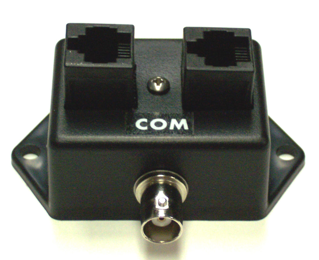
An installer can use a fixed attenuator with one dB steps that can be but in series with jumpers to reduce the cost of a switchable attenuator. One such low cost unit is called the IPMT-3. It has three fixed attenuators 1, 2, and 4 dB steps that can be put into any configuration from 1 dB up to 7 dB to test for a reasonable amount of Signal Margin. If you put the 4 dB attenuator in line with your IP video network cable “Looping Through” the attenuator and the monitor displays a steady signal, then you can be assured that the Signal Margin is large enough to guaranty non interrupted operation of that cable run. It is a quick test, but very important to know that your signal levels are not on the edge of failure before you leave the jobsite.
Measuring IP Levels Precisely:
To make precise measurements of signal level, the installer must know the power level of the Camera and Recorder first. As specified, the level is supposed to be 0.0 dBm. But in most cases, it is not even close with some manufacturer’s equipment. We have measured Power Levels as high as +13 dBm on some of the equipment that is for sale from Overseas. I think they have established a de-facto standard level higher so that the signals will have a better range over the network cable.
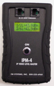
Since one of the factors of critical concern in the IP System installation is the Near-end and Far-end Cross-talk which is directly associated with the transmission levels, and that these two transmission levels directly affect this condition, dis-similar levels would be just asking for a cross-talk disaster. In any event, it is necessary for the Installer to make this measurement directly with some type of dB meter that can monitor the operating levels of the IP signal without interfering with or loading the signal path. This meter must have a loop through 8P8C set of connectors be portable if possible. There is a meter that meets all the requirements of IP level measurements called the IPM-4 IP Camera Master Power Meter.
Next the installer must know exactly how much Cable Loss the Network Cable has and how much signal level he is delivering to the far end of the network cable and this too can be measured directly with the IPM-4 Signal Power Meter.
The IPM-4 meter is used to measure the near end and far end signal levels simultaneously and display the dBm power levels on the LCD display noted by their wire pairs. This way if you are at the camera end you can measure the camera level “Near End” and the NVR or switch level “Far End” at the same time and determine the network cable loss all at a glance.
The next test that the IPM-4 does is to measure the Balance the near end and far end signals. Since IP signals are sent as a balanced transmission, any imbalance will cause additional losses in the signal. This balance is measured in dB and can tell you if your cable is unbalanced or if the equipment at either end of the network is damaged or defective. As an example, a lightning strike can cause one side of the balanced transmission to have a reduced level output, every bit of this unbalance is rejected at the receiver end and adds to the overall signal loss. This balance measurement will immediately measure that kind of loss and direct you to the damaged equipment or network cable so you can address the problem quickly.
Another measurement the meter gives you is called Common Mode. This measures the Common Mode interference that is caused by cable manufacturing variations and also any outside interfering signals that get into your IP cabling. If a cable has been damaged during installation or sometime later or an interfering signal is getting into the transmission by close proximity, the Common Mode reading will indicate a problem level and alert you to the issue, so you can solve it before you leave the install.
All of the necessary information to assure that any given IP Picture Transmission system has sufficient level to operate correctly can be obtained directly with an IPM-4 Signal Power Meter. All that is necessary, is to assure that the originating Signal Power, when reduced by the Network Cable Loss, results in a power level that is greater than the power that is necessary to operate the Recorder or any switches and with a quick margin test to guarantee that the system is not on the edge of margin failure using the IPMT-3.


