IP VIDEO TRAINING MANUAL
IP VIDEO TRAINING MANUAL
By: Don McClatchie
Since the introduction of digital IP cameras into the CCTV market place their use has been on the rise. The installation of this new digital technology requires that the installer learn new skills and have new knowledge. This article is a good read for anyone wishing to learn more about IP camera installations and problem solving.
CABLE:
The two most common cable types used for IP video installations are referred to as CAT-5e (Category-5e) and CAT-6e (Category-6e). The standard requires that the wire be #22 to #24 AWG stranded or solid. The stranded wire is more flexible but does not mate well with insulation displacement type connectors. If you are going to assemble your own cables it is suggested that you use solid wire with insulation displacement connectors.
A typical IP cable has 8 wires arranged in 4 pair sets. Each wire pair is twisted with a different number of turns per meter to reduce crosstalk. This process reduces the crosstalk between wire pairs and is a vital system requirement. Each wire pair is color coded for identification when wiring the connectors. All 4 pairs of wires are covered in a plastic jacket to protect the wires from abrasion and also functions as a strain relief for the cable connector. Some wire types have a spacer between the different wire pairs to separate the pairs to better isolate the signals and to act as a strain relief and to stiffen the cable. Here are some of the specifications for CAT-5e.
Characteristic Impedance 100 Ohms
Propagation Delay 5.0 nano seconds/meter
Inductance 525 nano Henrys/meter
Capacitance 52 pico Farads/meter
DC Loop Resistance .187 Ohms/meter
Wire Gage #24 AWG
Temp Range -55 to +60 Deg C
Dielectric Types
FP Foamed Polyethylene
PE Polyethylene
FFEP Fluorinated Ethylene Propylene
FEP Teflon
AD/PE Air Dielectric Polyethylene
Wire Pair Twists
Brown 51.7 Turns/meter Orange 56.2 Turns/meter Blue 64.8 Turns/meter Green 65.2 Turns/meter
CONNECTORS AND WIRE TERMINATION:
The connector used at both ends of the IP video cable is called an 8P8C connector commonly referred to as an RJ45 connector. The term RJ refers to a “Registered Jack” and the specifications for the RJ45 connector used in the telephone industry are not quite the same as the 8P8C connector for IP cables. However, as industry slang the two terms are used interchangeably.
The most common and lowest cost 8P8C connector uses the insulation displacement method to make the electrical connection to the pins and crimp a strain relief using the outer plastic jacket.
There are many manufacturers of crimp tools for the 8P8C connector, all of them terminate the pins to the wires and form the strain relief in one operation. Some simple wire preparation is required before you can crimp the connector onto the cable. First you must cut or push back the outer jacket of the cable to expose the wires then trim the wire ends so that they are all the same length. Next un-twist the wire pairs just enough to put them in the color coded order. Then insert them into the connector all the way down to the end of the connector and crimp it with a special tool. Once you have wired the network and connected the camera and NVR “NETWORK VIDEO RECORDER” you should take a moment to check the signal quality of the Physical Layer of the network.
PHYSICAL LAYER SIGNAL LEVEL:
The IP cameras have many benefits for the installer and the customer however they also have some drawbacks and special concerns that must be addressed. Perhaps one of the most obvious drawbacks is the maximum distance limitation of 100 meters or (328 feet). Although with good cable you can extend this distance by about 40% to 500 feet doing so is not suggested.
The reasoning behind this has to do with what is called the digital cliff or fail point of the camera signal at the maximum distance. One of the best parts about the IP camera signal is that the picture does not degrade with distance unlike analog video images that suffer from cable slope loss that make the pictures look dull and lacking in brightness of color and sharpness of image. However, the digital picture will fail cataclysmically just at the maximum distance and totally fail to render a picture at all.
At this point the equipment will sometimes flash the picture on and off at a slow rate of speed making the picture un-usable and then finally go off entirely. The technical cause for this digital cliff failure is that high level data from the near end equipment gets into the low level received signal from the far end and interferes with the decoding of the data. The data signal is scrambled by the interfering cross talk and as the cross talk becomes stronger the Bit Error Rate increases until the digital decoder cannot reliably tell a one from a zero and the communication breaks down. So, it is the near end cross talk levels that primarily control the maximum distance that an IP camera signal can go. Also, the amount of signal that exists above this fail point is referred to as the signal margin.
It is important to note that network cable quality largely affects this cross talk and signal margin. This cross talk should be measured at both ends of the cable when you install an IP camera. The measurement must be taken at both ends of the cable because the system has a two-way signal that exhibits the same type of cross talk at both ends of the system and when the receiver at one end fails the entire system stops transmitting from both ends and the system goes down.
Systems tests indicate that a difference of 10dB or (3.16 times) the level from input to output on either end of the system is enough to cause a failure of communication between the camera and the receiver or NVR.
This difference is measured at the fail point and does not take onto consideration that a margin of 3dB should be available to account for small changes in the cable loss or mechanical changes in the cable due to temperature or condensation variations and physical movement all of which affect the overall loss of the cable.
It is a good idea to measure the near end and far end signals levels on every camera installation you do so that you will know for sure what the levels are and have the confidence of knowing that they are within operating tolerance with enough margin to guarantee operation under all circumstances.
There is a commercially available low-cost meter that can measure these IP camera signals levels called IPM-4 IP VIDEO MASTER. This meter will measure your IP signal levels in both directions and give you the piece of mind you need to know the levels are correct and that your cross talk is manageable.

IPM-4
This meter will also measure the level of balance coming from the equipment and the delivered signal balance after traversing the network cable. Network cable quality will affect the signal balance and create excess loss in the system that can cause picture failure to occur. The meter also measures the Common Mode signal loss. This loss is caused by the network cables capacitive and inductive effects on the IP signal.
Use this meter to guarantee that your IP video installations will operate at the correct levels and that you have enough signal margin to continue to produce reliable pictures even when signal level changes occur.
PHYSICAL LAYER DISTANCE LIMITATIONS:
IP video does have its limitations and when you reach those limits you will get a total failure of the system to deliver any kind of a picture. Unlike the old analog cameras that would give you a dull washed out picture when the signal level was too low, IP cameras will give you a perfect picture until the cable loss reaches beyond the minimum allowable signal and then you suddenly get no picture at all. This effect is called the digital cliff, because, like walking off a cliff, everything is great till you take the last step off the edge and then all is lost.
IP VIDEO MARGIN is the amount of signal level above the digital cliff that you have in your system to prevent a failure from occurring. The question is how much margin is there in your IP video system, how close are you to falling off the cliff, and how can you measure it?
First let’s look at what causes this loss of the network signal. Signal level loss and high frequency roll-off in the network cable also called “cable slope loss” are the main causes of most failure. Reactive loss is the predominant loss of signal level and is caused by the distributed inductance of the wires and the distributed capacitance between the wires with a small additional loss due to the loop resistance of the wire. So what effects cable loss the most is the insulating material, twists of the wire and the uniformity of manufacture of the cable, not so much the gage of the wire although increasing that does help some.
The rate of wire twist and uniformity of twist strongly affects inter-pair cross-talk between active pairs in the cable and ultimately this sets the maximum distance that a cable can be used. In the manufacturing of cable, the magnetic and electrostatic forces within the network cable must be precisely controlled to prevent Common Mode cable loss. When all the equipment is working correctly common mode loss is caused by slight mechanical defects in the manufacturing of the cable.
Small changes or irregularities in the twist of the wires or non-uniform insulation thickness on the wires can cause a long cable to have unusually high common mode loss. Network cable loss is also affected by the temperature and humidity, not to mention water infiltration into the cables outer jacket and wire insulation. This common mode loss will directly affect the maximum distance you can go with a network cable and it can change with time. Temperature effects are a daily change in the loss of the network cable. However, humidity and the water intrusion is a lasting slowly progressive loss that will take the system down over time.
The consistency of the rate of twist and the diameter of the insulation must be very closely controlled over the entire length of the cable. Some manufactures control these parameters better than others, so if you find a good manufactured cable stick to using that brand for repeatable results. The manor in which the cable is handled and installed will also have a great effect on cable loss and over all system integrity.
When installing network cable try not to stretch the cable when pulling it into conduit, this permanently changes the wire diameter and insulation thickness damaging the cable and creating greater loss in the cable. Also twisting, kinking, or bending the cable in a radius sharper than 5 times its diameter will create additional loss in the cable.
So now that you have installed your IP system, how do you test for the margin? What you need to know is how much additional loss can the system take before it fails and how close are you to having a failure? You will want to know if the system is on the edge of the digital cliff before you finish the job, so you can walk away with confidence that the system will continue to operate when cable losses change slightly.
The easiest way to test for this margin is to use the IPMT-3 IP VIDEO MARGIN TESTER to insert a know amount of loss in steps into the signal path and see how much additional loss the system can stand and still deliver a picture. This loss is measured on a dB scale, and you should have at least 3 dB margin for a safe operating system. A loss of 3dB is the equivalent of a 29% drop in the operating level of the system. By using the other loss steps on the unit, you can determine if you have enough margin to reliably operate the system under all conditions. This unit will insert up to 7 dB of attenuation in 1 dB steps, so you can precisely determine your system margin to guarantee reliable operation.
The IPMT-3 is a low cost inline attenuator for testing IP video margin equipped with 8P8C connectors to fit your network cables directly. Simply loop your IP video signal through the unit starting with the highest attenuation and when the system displays a picture you will know the amount of margin your system has and then you will know with confidence how much additional loss the system can withstand. Most importantly you will know your system is not sitting at the edge of the digital cliff waiting to fall off. Measuring this margin is a must for all installations to give you the security of knowing your system is capable of withstanding additional loss and still operate properly. You can also use the unit to perform periotic testing to insure, that you maintain your margin of operating safety.
.
PHYSICAL LAYER SIGNAL BALANCE:
The IP video signal uses a balanced transmission method to deliver its data to the opposite ends of the network cable. By design a balanced transmission system sends equal but opposite signal polarities on each of the two wires in the pair. So, when one wire is showing a positive signal the other matching wire is showing a negative signal. In fact, the balance on this type of signal transmission is critical to proper operation and affects the maximum transmission distance directly.
Let’s examine how the signal is generated at one of the transmitting ends. Inside the camera electronic circuitry digitizes the picture information (light) into an electrical signal and by the time it reaches the output connector the signal must match the standards of a network “PHY” or physical layer signal. This layer has standards for its level, balance, and common mode interference. Once the digital signal is converted to a serial data stream and ready to transmit it is converted to a balanced transmission by the output driving amplifiers.
It is critical that these output driving amplifiers have a very precise and equal balance on the two sides to prevent any unbalanced signals from being transmitted. Any unbalance in the signal that reaches the receiver at the other end of the system will be cancelled out as a natural function of the receiver. All IP video equipment uses some form of common mode input circuitry that effectively cancels all unbalanced signals, so the cancelled signals are lost. If the unbalance is severe enough this loss will adversely affect signal reliability or cause total loss of operation. IP video signal un-balance is caused by the equipment originating the signals at each end of the network cable and by the cable itself.
So, what can cause the equipment to go out of balance after the installation? Lightning damage is the most common cause of un-balance in an IP system, followed next by ground-loop damage to the IP equipment, and then finally poor quality or damaged cable.
Lightning can damage the output driving impedance inside the IP equipment even if the lightning is not a direct strike, and that has the affect of lowering the output level and if it causes a permanent imbalance in the output signal that too will cause level loss at the receiving equipment. When the lightning strikes a high voltage can get into your equipment through the local ground and generate extremely high current flow in the output circuitry, that usually blows the resistive coatings off the resistors or damages the semiconductors and it all happens so fast that the coating on the resistors are not even singed.
Ground-loop can have the same affect of damaging the output impedance of the IP equipment over time and upsetting the balance of the signal. With an analog video signal, a ground-loop problem can be seen on the video image as a series black horizontal bars on the picture screen, but with an IP digital signal you can no longer see these ground-loop interference signals even though they will damage your equipment by excess 60 Hz AC current running on the wires.
This ground-loop current will enter your equipment through the ground of one piece of equipment and travel to the other piece of equipment by the balance wire pairs connecting them. The additional AC ground-loop voltage boosts the current flow in the electronics and slowly cooks the resistors until there resistive values change finally causing IP video failure.
If you install an IP camera, and a few months later you have to replace it and then a few months later (about the same amount of time) you have to replace it again you should be looking for ground loop issues. Ground-loop can be the silent killer of your IP equipment.
Cable quality issues can cause a well-balanced IP video signal to go out of balance and create excessive loss in the system. Cable that is poorly made or damaged cable is hard to see physically but can be measured to find out how well it maintains its balance from one end to the other. When a cable is manufactured great care should be taken to see that the insulation has a uniform thickness over the diameter and length of the conductor and that the twists in the wires are also uniform and repeatable. Any non-uniformity of the insulation will cause an imbalance in the capacity of the transmission line and create an imbalance that will be cancelled at the receiver. Damage to the cable like stretch cables or too sharp a bend radius or cable that has been flattened by being smashed or particularly wet cables can also cause un-balance even with a good manufactured cable. Even a person stepping on a cable can cause damage to the balance.
It is a good idea to check the balance and levels on every IP video installation you do to be sure your system will stand the test of time and temperature and weather before you leave the job and when you are trying to find the source of an IP video balance problem it is important to know whether to go after the cable or the equipment rather than just replacing things until it works and then hoping that you got it fixed. So, what you need is a device to measure these levels and balance that is easy to use and low cost.
The IPM-4 digital video level meter is used to measure the signal quality of an IP video network. This low-cost meter makes 6 different level measurements to give you assurance that your IP video system is working within specifications. It measures the output levels of both the camera and the recorder end of the system in dBm, so you can check the near-end and far-end signal levels and cable loss simultaneously. The meters unique design also measures the percentage of signal imbalance in that exists on both the sending and receiving channels which contributes to cross-talk and increases the bit error rate in your digital video. Then it measures Common Mode signals in dB, a form of interference caused by phase and amplitude variations that also causes video failure.

IPM-4
PHYSICAL LAYER COMMON MODE SIGNALS:
Unlike coaxial cable the network cable has no external shield covering the transmission wires to prevent outside interfering signals from getting onto the wires and mixing with the signal, this is done to reduce high frequency signal loss that a ground shield would induce and with out it significantly reduces the cost of the cable and increases cable flexibility. Instead of shielding the network cable as it is with coaxial cable, the network cable uses a different method to reduce the level of outside signals from getting onto the wires and interfering with the IP video signal.
All network cables are manufactured with twists in the individual wire pairs, this is vital to the proper operation of the IP system. It may not be noticeable to the naked eye but each of the pairs of wires have a different amount of twist per foot, this is also extremely important to reduce cross-talk in the IP system transmission. The twists alone do not prevent interfering signals from getting onto the wire pairs and in fact any interfering signal that is nearby has an unshielded direct path right onto the wires. However, the fact that the wires are twisted will cause the interfering signal to be evenly distributed on both wires and this helps the system remove the interference at the receive end. Interfering signals and crosstalk are the two main factors that limit the maximum distance any network cable can be run and so suppressing these interfering signals is vital for a successful IP installation.
So, what is Common Mode Suppression and why is it important? In a balance system each wire pair has an equal and opposite polarity on it at any one time. So, at the receiver end of the transmission we can say with great certainty that any signal that is the same polarity on each of the two wires at the same time is an interfering signal and can be removed. Amplifiers at the input of the IP receivers are designed to remove any part of the signal that is the same in phase and amplitude between the two wires instantaneously.
The removal of all signals that are common to both wires is where the term Common Mode comes from and it works very well as it relates to outside interfering signals. However, any part of the original wanted signal that is converted to a common mode signal in the wire run will also be removed and that is seen as a loss of the intended signal.
So how does the intended signal get converted to a Common Mode signal in the wire run and how can it be prevented? Let’s look at the different ways Common Mode signals are created from the intended signal. The primary culprit in Common Mode conversion is within the network cable itself. Poorly manufactured cables will create common mode signals all by themselves and cable can be damaged when installed and create the same effect. The actual reasons for this are mechanical non-uniformities in the manufacture and handling of the cable.
Starting with the single wire itself a non-coaxial application of the insulation that is not the same thickness all around the wire will cause unequal capacity to surrounding wires and its own wire pair.
This capacity change will cause high frequency losses to be different between the two wires in a pair and this will allow external sources of interference to enter the two wires with different levels and so the signal will not be removed in the receiver. For a “perfect” exclusion of outside interfering signals using common mode suppression, the wire cable construction and twists would have to be theoretically perfect. To the degree they are not, the outside interfering signals will get in. The better the cable construction is the less interference you have, that is why cable with higher frequency ratings cost more.
In the manufacturing process the wire is drawn down to size the diameter of the wire gage. If the wire is not the same size both the inductance and the capacity of the insulated wire will vary and this in turn will cause a percentage of interfering signal to become differential and it will be received as interference.
To the degree the twists in the wires are not uniform over the length of the cable cross talk between the wires will cause interference in the signal. If your network cable uses a separator non-uniformity of the separator between wire pairs will cause a small amount of interaction in the transmitted signals and so a reduction in the distance you can use with that cable.
Cost is not always an indicator of good quality network cable. Using a higher grade or Category of cable is usually a good way to get longer runs that will work well. But in the end trial and error or measurement is the only true test of any cable. Try to use the same manufacturer whenever you can and that will reduce your installation variation. Damage to the cable like stretched cables or too sharp a bend radius or cable that has been flattened by being smashed or stepped on and particularly wet cables can also cause un-balance and induce common mode even with a good manufactured cable.
So, besides the maximum cable length limitation how would the technician know which cable is better than any other cable or for that matter whether any system is near the digital cliff (fail point)? The easy way is the measure the signal level, balance, and common mode for confidence. The meter must be able to measure these three things to give the installer the assurance that the signal meets the minimum operating specifications for prolonged operation in any environment.
The IPM-4 digital video level meter is used to measure the signal quality of an IP video network. This low-cost meter makes 6 different level measurements to give you assurance that your IP video system is working within specifications. It measures the output levels of both the camera and the recorder end of the system in dBm, so you can check the near-end and far-end signal levels and cable loss simultaneously. The meters unique design also measures the percentage of signal imbalance in that exists on both the sending and receiving channels which contributes to cross-talk and increases the bit error rate in your digital video. Then it measures Common Mode signals in dB, a form of interference caused by phase and amplitude variations that also causes video failure.
LIGHTNING STRIKES:
LIGHTNING HAPPENS. You cannot control it, and when it happens near an IP Picture Transmission System, the differential current flowing in the ground and the twisted Pairs carrying the digital picture information can be enough to damage the terminating resistors in the system changing the value of those resistors from 100 Ohms to some other value. When this takes place a reflection of the digital signal will occur and if this resistance change is large enough, digital errors will be introduced into the receiving equipment that can cause intermittent failure or complete inability to transmit a picture.
Of course, a direct lightning strike will completely blow out the terminal equipment resulting in a charred mess but a NEAR MISS can cause resistance change that is not visible to the casual observer and still cause intermittent picture failures. Even the IP cable itself can be damaged by close lightning strikes. If you work in an area frequented by lightning storms, some of your IP picture problems could be caused by a close NEAR MISS. If there are no grounds attached to your IP video camera your system will be safe from all but the closest of lightning strikes.
Even if the Camera is not actually grounded a nearby lightning strike can induce a high voltage into the “local ground” and even a very small capacity from that local ground to the Camera will be sufficient to cause direct damage and/or differential currents in the twisted pair that can damage the driving and terminating resistances. Most IP video transmission systems are very short by their nature, but lightning can induce a high voltage on one side of a building relative to the system ground applying a very high local ground voltage directly into the associated equipment in the building.
Lightning Arresters are used to protect people from lightning by diverting the high voltage spikes to a local ground however at the same time they are protecting people from electrocution, they are also re-routing that lightning current directly into any equipment that happens to be grounded.
Another possible lightning damage issue is with the “POE Power Over Ethernet that is applied to the IP system to power the Cameras. With the rather high voltages encountered in lightning strikes a very small capacity between the Camera, Recorder, or IP Cable and the local ground can induce differential currents and voltages into the IP System to cause the IP Camera system to default. Normally small near miss strikes will only cause the P.O.E. power supply to reset due to over voltage if no damage has occurred in the P.O.E. electronics. In P.O.E. power systems there is a resistor that is measured to determine what voltage to apply to the system and if that resistor is damaged by a strike, the P.O.E. system could supply the wrong voltage to the equipment or fail to supply any voltage at all. It is a good idea to make up an inline connector that connects the IP signals and gives you access to measure the P.O.E. voltage and put that in your tool box to check the voltage when in doubt. Or you can use a POET-1 to get a reading.
.
. POET-1
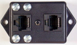
The POET-1 allows you to access the 4/5 – 7/8 pairs, and the 1/2-3/6 pairs to make voltage measurements easily. All 8 wires loop through giving you access to the P.O.E. pairs for volt meter measurements. In the past about the only way of discovering which piece of equipment is damaged by a close lightning strike, has been to replace equipment until the system works again. This is a very time consuming and expensive process.
The IPM-4 Meter can be used to discover just which piece of equipment needs to be replaced in the case of lightning strikes without having to stock multiple Cameras and Recorders, so you can save time and money when doing repairs.
With this meter you can discover exactly which piece of equipment is damaged by the close lightning strike. This meter will measure the actual Network Cable loss as well as the amount of Common Mode loss that is present in the cable, and also calculate the decibel loss directly attributable to the IP camera output Common Mode signal in the IP System.
There are two different kinds of loss on IP cables, the normal Cable Loss over any particular length of Network Cable, and an additional loss attributable to the amount of Balanced Differential signal that has been converted into an unbalance COMMON MODE signal.
The portion of the digital signal that has been converted to Common Mode signal will be cancelled out at the received at the end of the IP system. This additional loss directly caused by conversion to Common Mode is called the EXCESS LOSS and it is over and above the normal Network Cable Loss.
The IPM-4 measures the Normal Loss of your Network Cable, the degree of signal conversion to COMMON MODE and the EXCESS LOSS introduced by that conversion process. The IPM-4 will make these measurements with the Camera and Recorder in place by using that equipment as the signal source.
ADDING ACCESS CONTROL TO IP VIDEO:
Access control has been evolving to meet the requirements of the new IP video technology and broadcasters are always looking for new ways to have control over their systems. Now it is possible to add contact relay access control to any IP video without degrading the picture quality or functionality of the IP system.
Remote access control can be added to an existing IP video surveillance system to monitor gates or doors and also control access to the area by remote control. The usual installation uses wire pairs to make the electrical connection for remote control, but when the cost of running those wires include chipping up concrete, digging a trench or breaking into walls it is now possible to get the contact control signals onto the same network cable used for the IP video signal.
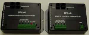
The IP4x4 is a unit that will give you 4 contact switch relays in both directions to add remote access control to any IP video network cable. The control signals go both ways on the cable and will share the network cable with the IP video data without affecting picture quality. In fact, this system will work on any twisted wire pairs without the need for an IP signal. So, you can use this anywhere twisted wire pairs are available.
.
. IP4x4
At some remote access control sites, the old wires have gone bad due to direct burial corrosion, or wire breakage and when the cost of running new wires is prohibitive you need to start looking at alternate paths for your control signal, and this is when the IP4x4 will really pay off for you, just jump onto the IP video network cable and control up to 4 contacts both ways. If there is a network cable going your way, use it to get your job done. Whenever you come up short of wires for contact relay control, use this equipment to get the connection made. One-way units are also available for four channels in one direction.
IP VIDEO FAILURE ALARMS:
When you discover tampering in a CCTV security system it normally occurs at the most vulnerable and exposed part of the system, the IP video camera. Normally the camera is mounted outside of the security of locked rooms and under the eye of the public. There are many ways to disable an IP video camera and render it useless.
For instance:
You can cut the cable carrying the video or power.
You can stick a pin through the video cable and short out the picture.
You can cut the power to the camera or remove it completely.
Most tampering employs one or more of these methods to disable the camera, and if the tampering goes un-noticed for any length of time the criminal will get away with the crime and there will be no video record of it.
One of the most common examples of tampering occurs at the loading dock where products are stacked up before or after a delivery. The criminal will block or disable the IP camera and then load the products onto a truck at the dock then just drive away. If you had been alerted to the loss of the IP camera video in real time you could have respond quickly to prevent the criminal from making off with the goods. It is a good idea to sell your customer on video loss detection before a loss occurs.
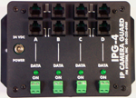
There is a device specifically designed to detect the loss of an IP video camera due to tampering, it is referred to as the IP Video Camera Guard “IPG-4”. The IPG-4 will identify tampering or failure of Data from IP cameras when it occurs, reducing the liability associated with extended and undetected loss of area security when cameras are rendered in-operative. The IPG-4 increases the level of security by providing an alarm contact output to protect the integrity of the Data system.
The IPG-4 Camera Guard can be connected anywhere between the IP camera and the digital monitor equipment in the data path. You can connect it near the IP camera to activate a local alarm, or at the monitor location to alert guard personal or shut down equipment. It provides a “Loop- through Input” that will not affect the picture quality or the data level. The unit detects a loss Data level that indicates the power to the IP camera is off, the cable is “disconnected”, or the Wireless Transmission system/Fiber optic system has lost its data signal.
IPG-4 IP Video Guard
Use this unit in any IP installation that requires guaranteed continuous data monitoring. Use the IPG-4 to monitor the IP cameras in sensitive areas like loading docks or any area subject to the unauthorized movement of product or stock. Or use it to determine if you have an intermittent failure problem in any IP data system.
The IPG-4 IP Camera Guard system supervises the continuity of four separate data signals from IP cameras. This supervisory system will identify loss of any data signal due to removal of the camera, loss of power to the camera, a camera cable disconnect, or a defective camera. The IPG-4 supervisory system continuously displays the “DATA ON” condition of 4 IP cameras, with individual L.E.D. indicators for each data channel. Use it to monitor IP video cameras and shut down un-attended gas pumps if the video camera is tampered with.
Normally Open or Normally Closed Alarm contacts are provided for each channel to send an alarm or activate equipment when loss of video occurs. These contacts are field programmable for Normally Open or Normally Closed contact operation. This unit can be connected to a local alarm to alert monitor personnel that an IP camera is being tampered with or send a message to a remote site by connecting the alarm output to external dialing equipment. It can be used to shut down equipment such as gas pumps when the data fails. The IPG-4 has an easy mounting flange that will mount to any surface with just two screws and is supplied with a 24 VDC power cube. This unit can also be used to protect and alarm any IP equipment placed into public areas where theft of equipment is a concern.
NETWORK SWITCHING WITHOUT PROGRAMMING:
Some of our customers have indicated that they would like to switch off a network IP camera under special circumstances with a simple switch that their customers could use and if the camera is supplied with power that is non-P.O.E. (Power Over Ethernet), then you can just cut the power to the IP camera and the network goes dark. In other circumstances, the customer wants to choose between two cameras at different locations showing only one camera at a time. Of course, they could go into the NVR set-up using a keyboard and shut off the camera by programming means or unplug the network cable and plug in the other camera cable, but that is not very convenient and well beyond most of their customers ability.
These applications include courtroom control of IP camera’s, sometimes the judge wants to be able to shut down the camera at certain times. In jails and prisons for privacy reasons some security areas could be blacked out normally but come on in emergencies to record the situation. One application exists in hospital critical care rooms. When the room is being used for critical care and being actively monitored by nursing staff they want the camera to be on, but when the room is being used for normal care they want the camera to be turned off. Can you think of a situation where your customer might want to turn off a camera without having to unplug it manually or share one more camera on an NVR that is already at full capacity? When your customer just wants to add one more camera for a special application this unit will allow the customer to switch to it when they want to without accessing the NVR programming, which most customers would have a problem doing.
IPX-24 BLOCK DIAGRAM
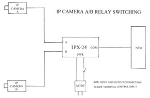
With analog camera signals these applications were accomplished with a simple video switch. But now with the new network cameras it is not as easy to do with just a single relay. To do the job the network switch must switch all 4 pairs of network wires and maintain the proper line impedance to reduce high frequency reflections that can reduce the quality of the IP network camera signal. It also must handle and switch the P.O.E. signal as well.
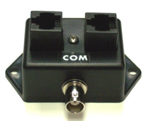
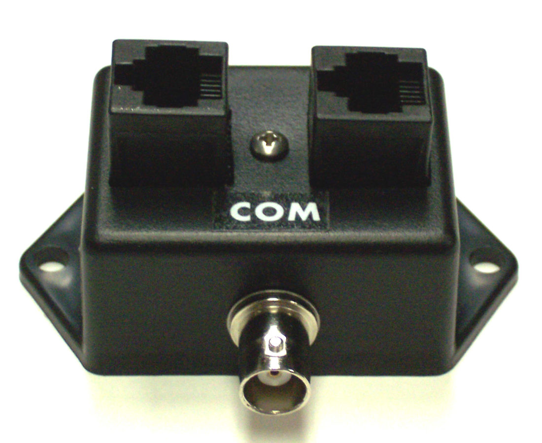
There is a new low-cost IP camera network A/B switch that can serve as a camera cut-off or an A/B camera switch. This product is called the IPX-24 and will handle two IP camera network signals and switch between them using an external AC or DC 24 Volt source. If you need to use 12 Volts AC or DC then you can order the IPX-12 made for mobile IP video applications.
This network switch will handle all forms of the P.O.E. signal as well as the data to switch between two camera network signals. This switch uses an external voltage for direct relay switching to route the P.O.E. and data. When this switch disconnects a network camera from the NVR and P.O.E. source, the camera will also power down reducing the operating hours on the camera and eliminating the possibility of interference from the un-used camera.
The control voltage that operates the switch can come from a source of 12 or 24 Volts by way of another relay or a local switch to make installation and operation easy. Also, this unit can be used on any type of network that uses 8P8C (RJ-45) connectors. The unit is fully isolated and has an LED to indicate which network is active.
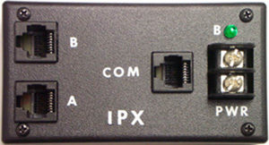
IPX-24 IP Network A/B Switch
IP CAMERAS ON EXISTING COAX CABLE:
New IP cameras are gradually replacing the old analog cameras in exiting CCTV installations to boost the picture definition and upgrade them to the new digital technology. In some cases, the running of new network cable for IP cameras is not economical or it requires heavy labor and disruption at the site of the installation. Many times, the old cable wiring has been buried in walls, run under concrete walkways or is in a conduit that is full and hard to service.
In most cases the old analog cable is intact and fully functional but cannot directly connect to the IP camera because the digital camera requires two pairs of 100 Ohm impedance wires for the two-way data communication and the single coaxial cable is 75 Ohm and not balanced. Of course, the most obvious problem is that the connectors will not fit together.
There is a number of IP to Coax Cable Adaptors on the market and some are better than others but all of them can suffer from an installation problem not related to their manufacture. When installing an IP over coaxial system there are some issues about the existing coaxial cable that should be addressed. These issues do not normally affect the analog signal but will heavily impact your installation of an IP over coax system.
The use of old 75 Ohm Coaxial Cable to transmit IP pictures can result in an intermittent signal due to loss occurring in the way coaxial connectors are attached to the Coaxial Cable. This has come to light during tests of IP picture transmission over relatively old Coaxial Cable. These cables transmit ordinary analog video without any difficulty but when used to transmit IP type picture signals these cables sometimes exhibit intermittent IP data transmission. So, what causes the intermittent data transmission? To understand why it is intermittent we need to look at the difference between analog and digital camera signals.
With analog picture transmission, there is absolutely no evidence of intermittent operation or transmission defect of any kind however when these same cables are used for IP picture transmission even for very short distances these cables will often not transmit an IP picture. Wiggling the connector sometimes brings the picture back but will not produce a permanent solution.
When this occurs, the problem is at the connector termination with the wire. The connector is suffering from a small resistance change on the center pin of the connector when it is wiggled, which is not enough to cause a visible amplitude change in an analog video transmission but is enough to cause a reflection of the data stream in a digital transmission so that the data becomes distorted and introduces errors in the data so that the IP pictures cannot be received properly this creates a high bit error rate preventing the decoding of the data.
This extra resistance may only be on the order of an Ohm or so and thus are not observed on analog video signals or noticeable with an Ohm meter but can completely block the IP picture transmission by inducing reflections in the signal.
This particular problem appears to occur due to inadequate crimping of the center conductor pin during wiring of the connector and can be remedied by SOLDERING instead of crimping the central coaxial wire to the center conductor of the Coaxial Connector. It is recommended that crimping of the center conductors be eliminated, and all center conductors be soldered to insure continuity of center conductors when a cable is used for IP picture transmission. Even small discontinuities on a moderately long cable can introduce reflections of the digital signal that can introduce errors in the received signal, thus preventing the transmission of the picture.
There is another issue with IP over coax equipment that you should watch out for and that has to do with the way the IP signal is transmitted on the coaxial cable. Some manufacturers use Half Duplex transmission to send the two-way data over one cable path by time multiplexing the signal, that is by sending one direction at a time so that each end of the system sends its information half of the time. This type of transmission should be avoided because it reduces the data transmission speed effectively reducing the bandwidth and delivery speed by half. Be sure to look for systems that transmit the data in both directions simultaneously with no reduction of data delivery rate. One such unit is the IPC-1 IP over coax adaptor.

IP Over Coax Converter
The IPC-1 allows IP camera signals to travel on existing RG59U or RG6 coaxial cables once used for analog cameras and will extend the operating range of an IP camera far beyond the 100 meter limitation of network cabling to over 300 meters (1000 Feet) of coax cable. This equipment operates in full duplex mode without reducing maximum network speed and requires very little installation time with absolutely no set up of IP or MAC addressing, so no configuration time is required. You can use this equipment with 10 Mbps signals all the way up to 100Mbps standard Ethernet IP signals. The IPC-1 will pass all forms of error detection and parity signals without interference.
This equipment can overcome network cable distance limitations and reach out to areas and locations traditional networking does not allow. Both the 8P8C (RJ45) IP input and the BNC coaxial cable connections are auto-terminated to guarantee proper termination. A bi-colored LED monitors the power supply and the Data signal integrity. Installation is a snap, just connect one unit at each end of the coaxial cable, then plug your network cables into a unit at each end, then apply power to the units. IP data will begin to automatically communicate and establish the link and then your video will appear at the other end.
PIGGYBACK SOLUTIONS FOR IP CABLES:
Now the IP camera only needs two wire pairs to communicate with the NVR. The NVR talks to the camera on one pair and the camera talks back to the NVR on the other pair, this is called (full duplex) operation and it uses wire numbers 1-2 and 3-6 as pairs. The only exception to the rule is the use of P.O.E. (Power Over Ethernet) that can use one or more of the remaining wire pairs 4-5, 7-8, for power distribution and even then, the power can be distributed on the active data pairs 1-2 and 3-6.
Provided there is no use of P.O.E. on wire pairs 4-5 and 7-8, it is possible to have those extra pairs of wires free for additional uses. Those un-used wires present a real opportunity to provide additional features that can be expensive to provide otherwise.
So, let’s look at what can be done with those extra free wire pairs. The first thing that comes to mind is to use them for another IP Camera. It is possible to use the second set of two pair wires to run another IP camera with out having them interfere with one another.
It is possible to piggyback two analog cameras on the two pairs of wires without interfering with the original IP camera signal or the other analog camera signals. Simply use passive video baluns (impedance matching transformers) to match the 75 Ohm BNC coaxial connectors to the 100 Ohm twisted pair wire and you have a clean path for two additional video signals. You can even add PTZ control of those cameras with RS422 control over the same pair of wires using the DLT/DLR-1 data piggyback equipment attached to the wire pair.
.
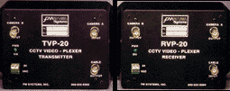
How about two video signals on the same twisted pair wire set by using a TVP/RVP-20 video di-plexer to get even more channels of analog video over the CAT-5/6 cable, again by using the baluns to match the cables.
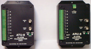
The extra pairs can obviously be used directly for contact alarm signals however you can expand this use from 8 to 160 contact alarm signals on just one pair of wires by using the ATU/ARU-8 system of relay contact multiplexing and the control signals can even run in opposite directions on the same wire pair. As with the other options this also uses video baluns to match the connectors and the impedance.
The next time you are quoting a job or surveying the jobsite, examine the possibility of using these extra wire pairs to sell your customer additional features with little or no additional wiring.
IP VIDEO SUB-BAND INJECTION
The IP video signal on the cable uses a bandwidth from about 10 Khz up to 50 Mhz or (100Mbit) of the RF spectrum. There is a portion of that spectrum that can be used without interfering with the IP video signal. This low frequency sub-band can be used to send signals for relay control and audio tones or any communication signals that have low frequency carriers. All you need is a way to band split the IP cable for isolation and a connector port to insert and remove the low frequency signals. As an example, you can use an LFI-1 sub-band injector at one end of the IP video cable to clear and inject the low frequency signal onto your IP network cable run, and then at the other end of the cable use another LFI-1 sub-band injector to break the low frequency signal out and remove it from the IP network cable.
. 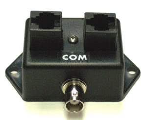
. LFI-1 pair
This product is used in pairs to inject and then remove the low frequency signal used for other types of communication on the existing IP network cable. This equipment will pass (Power Over Ethernet) P.O.E. on wire pairs 4-5/7-8 so you can power your equipment using P.O.E. With these sub-band splitters, you can use the SDI-C to put relay contact control onto your IP network cable or use the SDI-D to add PTZ (RS422) data control on the same network cable.
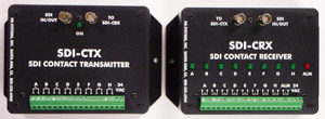
Contact Relay Control on SDI Video
SDI-C Transmitter and Receiver units
The SDI-C units will give you up to 8 relay contacts for control and telemetry on any coaxial cable or twisted pair wire system, and when used with the LFI-1 units can be inserted onto any IP video cable to use the existing wire cable to send both IP video and the contact control.

SDI DATA Transmission Set
SDI-D Transmitter and Receiver units
The SDI-D units will give you the ability to add PTC control or any RS422 signal onto a coax cable or twisted pair wire system, and when used with the LFI-1 units can be inserted onto any IP video cable to use the existing wire cable to send both IP video and the RS422 signals.
If you have a situation where it is difficult or impossible to run wire to get a signal through or the existing wiring is hard to reach, buried under concrete or inside walls and the cost of breaking into the cabling is prohibitive, give us a call. We have many unusual solutions to get your signal connected. Sometimes “thinking outside the box” can save you time and money or even make the seemingly impossible, possible. You can see these products and a lot more by going to www.fmsystems-inc.com and look in the product section or call me at: 1-800-235-6960


