FDNR Filter Design
By: Frank McClatchie
FM SYSTEMS, INC.
This design process enables designers to build Low Pass Filters that exhibit much higher accuracy than can be done with 10% inductors and 5% capacitors, using only 1% resistors as the required active components. At the same time, inductors created by the FDNR have very high “Q” and thus low loss, assuring a much flatter response curve than ordinary L/C filters. There are several “tricks” involved with these designs that will be discussed.
Since these filter designs use active components, the operational amplifiers used in the design must be able to handle the frequencies involved. In general, the operational amplifiers must be able to operate at a gain of unity without instability and have a cut-off frequency at least ten times the highest frequency that is to be handled. This not only includes the cut-off frequency but also the higher frequencies above that are to be cut off.
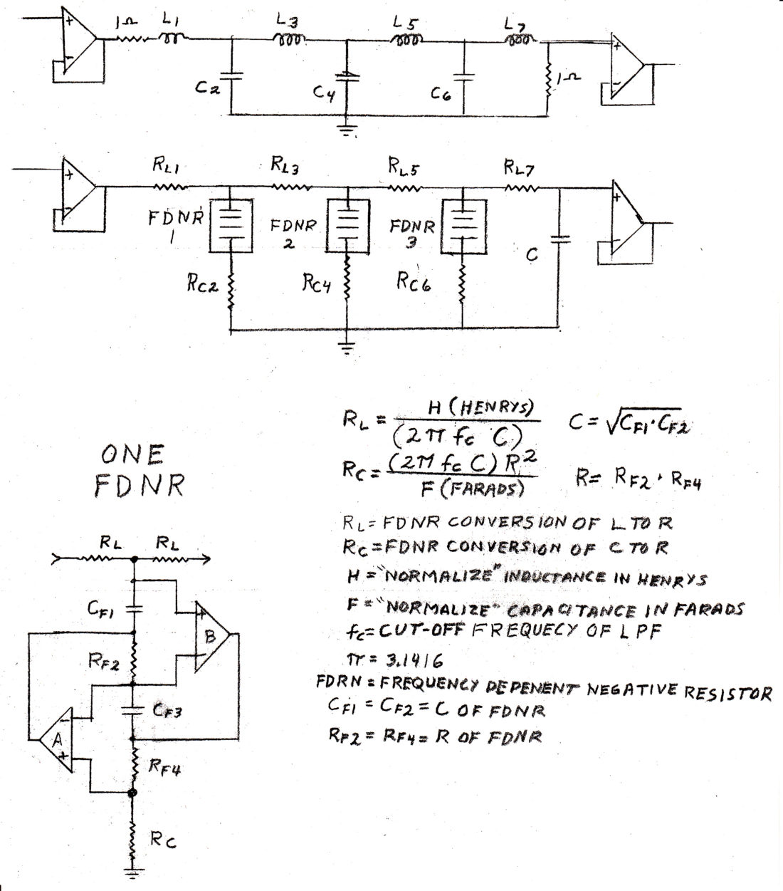
The FDNR has two terminals. At one terminal any RESISTER connected to that point becomes an INDUCTOR. At the other end of the FDNR any RESISTOR connected to that location becomes a CAPACITOR. The FDNR thus becomes a converter that can simulate either INDUCTORS or CAPACITORS, using only two operational amplifiers and two resistors and two equal value capacitors. Any number of FDNR’s may be connected in tandem to create any desired degree of in-band ripple, cut-off rate and total attenuation out of band. The cost of operational-amplifiers has gone down dramatically and high frequency cut off of the amplifiers has gone up dramatically, opening up an entirely new field in which the FDNR design process can be used to advantage.
To help understand the FDNR circuit, consider that the two ends of the FDNR are conceptually a single point. Therefore the two resistors which, are actually simulated inductors under the conversion of the FDNR, are thereby connected to the resistor at the other end which is actually converted into a capacitor by the FDNR as well. The result is that there are now two series inductors connected together with a capacitor to ground. An actual low pass filter, without using any inductors or capacitors as active components! Of course there are capacitors within the FDNR itself, which incidentally must be of high quality and not subject to temperature instability. These capacitors that are internal to the FDNR must be temperature stable so that the filter will have stable characteristics as well.By simply inverting the FDNR design, a HIGH PASS FILTER can be created.
The magic in the FDNR DESIGN process is how simple the calculations are to implement. First let’s set up some general guidelines. It is obvious that the op-amps must be fully operational at frequencies well beyond the cut-off frequency region of the filters themselves, Secondly, the resistors and capacitors that make up the FDNR circuit should be approximately equal at the cut off frequency (Xc = R). The two resistors are equal and the two capacitors are also of equal value. Any suitable values may be chosen.The actual FDNR design process is to first choose a “NORMALIZED” filter design that at least meets the permissible in-band ripple, desired cut-off rate, and total attenuation out of band. In general choose a design that meets the criteria and also has the fewest number of shunt capacitors in it. This is because it is necessary to install one FDNR (containing two op-amps) for each shunt capacitor. Once the “NORMALIZED” design is chosen, then it is only necessary to convert the Inductances and Capacitors in the “NORMALIZED” design to their equivalent resistive values for the FDNR design.
The termination of normal L/C filters often involves a sending end termination and a receiving end termination. However the FDNR filter must be driven by as pure a Voltage Drive (zero impedance) as is possible, so there is no sending end termination. The receiving end termination is the same as the FDNR impedance, that is, a capacity of the value of the internal FDNR capacitor terminates the filter.
RL = Resistor that is required to simulate the Inductor (FNDR conversion factor)
Rc = Resistor that is required to simulate the Capacitor (FNDR conversion factor)
H = HENRY value of “normalized” filter inductor.
F = FARAD value of “normalized” filter capacitor.
CFDNR = Chosen capacitor value within FDNR (Capacitive reactance at Fc approximately = RFDNR)
RFDRN = Chosen resistor value within FDNR
Fc = Cut-off frequency of the low pass filter
FDNR = Frequency Dependent Negative Resistor (a variation of the Gyrator).
RL = _________ H_________ (Calculated resistance value of filter inductance) (6.2832 x Fc x CFDNR)
Rc = (6.2832 x Fc x CFDNR) x RFDNR x RFDNR (Calculated resistance value of filter Capacitance)F


