EXTENDING DATA SERVICES TO NTSC VIDEO TRANSMISSION
EXTENDING DATA SERVICES TO NTSC VIDEO TRANSMISSION
By: Frank McClatchie, President FM SYSTEMS, INC.
The NTSC video signal format was originally devised to enable transmission of a good quality picture and the various special pulses necessary to synchronize the received picture with the transmitted picture.
About 82.8% of the time, the actual picture is being transmitted and 17.2% of the time is devoted to the various synchronizing pulses. While data may be inserted any time the picture is not being transmitted, engineering prudence would rule against interfering with the most critical intervals of time. In practice, and general industry consensus, only certain gated time intervals can be used for data transmission. These time intervals are known as line 10 through 20 on the Odd and Even Frames of the composite video signal.
Each line has a duration of 63.5555636 microseconds. With a maximum of 11.1 microseconds devoted to sync and other housekeeping tasks, then 52.455 microseconds are left for data. Since there are 10 lines available per frame and 59.939 frames per second, then just 31,441 microseconds are available for data per second. This is just 3.14% of the total time available. Not much, but significant and essentially free time available for transmission of other information. Lets see what can be done with this surplus time.
First of all we must find the portion of the frequency spectrum most congenial to data transmission to minimize errors created by the transmission medium. It turns out that there is a specific frequency band in any transmission system that is optimized for color TV transmission. The Envelope Delay, Differential Gain, and Differential Phase of TV transmission systems are especially pampered in the vicinity of the 3.58MHz Color Burst for optimum color TV transmission. For this reason data transmission must be synchronized with the TV Color Burst frequency.
A further motivation to synchronize with Color Burst is that it also enables the data decoder to use the Color Burst to precisely locate the received data in time. Synchronous demodulation thus becomes simply a matter of locking to the TV Color Burst (the same process as decoding Color in the picture).
Since one-half cycle of the Color Burst frequency is 0.139682557 microseconds and the active line time is 52.45556 microseconds, then a maximum total of 375.534 data units could be transmitted in a TV line.
Since fractional data units are not much use, we can transmit 375 data units per line. Considering each line as a Data Packet, then with various modulation schemes the number of bits transmittable per packet would range from 1.5KB/packet for Bi-level, 2-Phase to 24KB/packet for 64 QUAM. Depending on the data transmission rate desired, anywhere from one to ten Vertical Interval Lines per frame could be implemented. The maximum data rate for 64 QUAM would then be 24KB X 10 lines X 59.94 Frames/sec = 14.3856 MB/second. With only 3.14% of the time available, the 14.3856 MB/sec. rate looks promising!
Of course 64 QUAM may be pushing it a bit on a one-way transmission system where errors must be held to a much lower factor, so perhaps a 2-level type modulation scheme would garner the desired low error rate. In that case the data transmission rate would still 375 X 2-level X 10 lines X 59.94 Frames = 449.55KB/sec., while a 4 level code would be 899.1KB/sec.
Broadcast standard RS170 stipulates that line 17, 18, 19, and 20 be reserved for VITS, CUE and Control signals, so if these lines are avoided, only seven lines could be used for data instead of ten. Lines 17 – 20 are generally not used for these purposes in CCTV or Distance Learning applications.
While the TV Broadcasters and Satellite video transmission companies have long used some of this space for Vertical Interval Test Signals (VITS), Ghost Canceller Reference signals (GCR), Closed Caption Transmission for the hearing impaired, Videocipher audio transmission, and various other command, control, and alarm transmission systems; these channels are not now being used in CCTV or Educational TV.
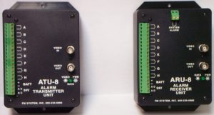
To cite one example of command and control using the Vertical Interval of a television signal, an Alarm Transmitting Unit (ATU-8) can direct route switching of a television signal through intermediate Route-Switchers to a specific destination by a code buried within the Vertical Interval of the Television signal itself. No exterior switching paths being needed. Other codes can also be sent along with the Television signal that could direct a tape machine at the receiving location to record the program or intercept existing on-the-air programs to distribute an Emergency Broadcast Announcement. In each case an Alarm Receiving Unit (ARU-8) receives these commands and directs the desired action.
CLICK HERE for more information
In summary, data transmission superimposed on video signals is an ongoing process today. Most of the lines in the Vertical Interval have yet to be used on most Television transmission systems. There is an opportunity to expand the use of these channels to general purpose or special purpose data transmission by packetising data into 52.38 microsecond increments.


