ALIGNING A CCTV TWISTED PAIR SYSTEM FOR MAXIMUM PERFORMANCE A PROPOSAL TO ESTABLISH A SYSTEM QUALITY MEASUREMENT STANDARD
ALIGNING A CCTV TWISTED PAIR SYSTEM FOR MAXIMUM PERFORMANCE
A PROPOSAL TO ESTABLISH A SYSTEM QUALITY MEASUREMENT STANDARD
Author : Frank McClatchie, President of F M SYSTEMS, INC. TEL: 1-800-235-6960
This article defines a procedure that enables a CCTV installer to obtain the best possible picture that any given Camera can send over Twisted Pair wires to any given Monitor. When the Camera and Monitor are connected together “on the Bench” with short wires, what you see on the Monitor will be the best picture that this Camera and Monitor can produce. No additional equipment can improve on that picture, baring that there is no defect in either the Camera or Monitor. Good Monitors will display all of the Lines of Definition that the Camera can produce.
Once connected together through long Twisted Pair wires “in the field”, you will at once notice a reduction in picture detail. If it is a Color Camera and Color Monitor, there will also be a noticeable reduction in color brightness or even no color at all. This condition is due entirely to losses that take place in the Twisted Pair wires and the Baluns used to connect into the Twisted Pairs. This signal loss can be corrected using video amplifiers and equalizers such as the CCTV Twisted Pair Picture Clarifying System.
SOURCE OF THE PROBLEM
Twisted Pair wire and the associated Baluns both create signal losses across the entire 30 Hz to 4.5 MHz span of frequencies encompasses by a video signal. The longer the wires the greater the loss of signal, until, with a long enough wires, there will be no usable picture signal left. The higher frequencies, which convey fine detail in a picture, suffer much greater losses than the lower frequencies which mainly contribute to picture brightness.
A high definition Camera (say 570 Line Definition) looses more of its rated Lines of Definition while traversing the Twisted Pairs than a low definition Camera (say 380 Line Definition) on any specific length of wire. After all, the 570 Line Camera has more Lines to lose that the 380 Line Camera. Therefore a long pair of wires will impact the received detail more on a 570 Line Camera than a 380 Line Camera, but the 380 Line Camera will never look better than the 570 Line Camera on any length of Twisted Wire. However, if an amplifier and equalizer is added onto a long Twisted Wire pair, and correctly adjusted, all of the Lines the Camera can generate will appear at the Monitor location, greatly improving the quality of the picture as seen on the Monitor.
JUST WHAT ARE LINES (OF DEFINITION) ?
Now that we have broached the term Lines of Definition, let us define the term as used in video. First of all, it has absolutely nothing to do with the number of horizontal lines that are seen in the picture! In fact, all CCTV Cameras (in the USA) create exactly the same number of horizontal lines in a picture (that number happens to be 480 lines in each picture). The video system does create 525 sync pulses per picture, but only 480 produce visible lines. What a statement like “570” Lines refers to when discussing the detail a Camera can produce, is actually the maximum number of VERTICLE lines that could be distinguished on a Monitor screen. If you tried to show more than 570 lines on the screen, instead of actual lines the screen would appear grey.
BAND WIDTH REQUIRED
The larger the number of Lines a Camera can show, the wider the bandwidth of the video signal (see TABLE 1).
|
TABLE 1
LINES BAND WIDTH REQUIRED |
|
| 330 | 3.1 MHz |
| 380 | 3.6 MHz |
| 400 | 3.7 MHz |
| 460 | 4.3 MHz |
| 470 | 4.4 MHz |
| 480 | 4.5 MHz |
| 570 | 5.3 MHz |
It can be seen from TABLE 1 that, for instance, a 380 Line Camera will be less affected by high frequency loss in a Twisted Pair than a 570 Line Camera, but then again the 380 Line Camera can never deliver the definition of a 570 Line Camera, even under the best of circumstances.
As Twisted Pair wires become longer, the losses increase at all frequencies, but high frequencies suffer much more loss than low frequencies.
One handy measurement for the low frequencies that affects mainly picture brightness and contrast, that can be easily measured using a CM-1 Camera Master, is the Sync Pulse amplitude. As the Twisted Pair get longer and longer, the Sync Pulse gets shorter and shorter. The Sync Pulse amplitude is an exact measure of the Twisted Pair loss at low frequencies because all Sync Pulses are the same amplitude at the Camera, so measuring Sync Pulse amplitude at the Monitor also measures the loss of brightness and contrast as the video picture traverses the intervening wire facilities and associated Baluns. The Sync Pulse amplitude is always the same, even when the Camera lens is capped.
A handy measure of high frequency loss that best reflects the Lines of Definition transmittable over the Twisted Pair wires is the measure of the Color Burst amplitude that is generated by a Color Camera and measured at the Monitor. A Color Burst is always the same at the Camera even when the Camera lens is capped and is not influenced by the actual picture transmitted. Thus the amplitude measured at the Monitor is an exact measure of the loss caused by the Twisted Pair and Baluns. This measurement, using a Color Camera, is an accurate measure of the wire facility loss even when the camera is later replaced by a black and white Camera.
THE KEY TO MEASURING SYSTEM PERFORMANCE
These two measurements (Sync Pulse and Color Burst amplitude), thus provide an exact and specific measure of the ability of any given Twisted Pair (and Balun at each end) to transmit a quality picture.
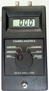
The easiest way to measure the Sync Pulse (SP) and Color Burst (CB) amplitude is with a CM-1 Camera Master. This is a digital, hand-held meter that reads these two (and also other) characteristics of CCTV video signals accurately in I.R.E. Units of measurement. All video measurements, world wide are measured in I.R.E. Units, so we must know exactly what an I.R.E. Unit is and why this measurement is universally used by the Video Industry.
WHAT ARE I.R.E. UNITS AND WHY ARE THEY USED?
The main reason for measuring in I.R.E. Units instead of Volts peak-to-peak is simplicity of the numbers created while measuring a video signal. For instance a standard amplitude video signal in Volts peak-to-peak and I.R.E. Units measure exactly:
| VIDEO COMPONENT | I.R.E. UNITS | VOLTS peak-to-peak |
| B/W (picture only) | 100 | 0.714285714———- |
| Color (picture only) | 120 | 0.857142857———- |
| Sync Pulse | 40 | 0.285714286———- |
| Color Burst | 40 | 0.285714286———- |
| B/W (peak to peak) | 140 | 1.00 |
| Color (peak to peak) | 160 | 1.142857143———- |
Notice that only the Black and White video signal (at 1.00 Volts peak-to-peak) is easy to measure in Volts peak-to-peak while all of the important parameters are easier to remember and use as a reference when video signals are measured in I.R.E. Units. It is no wonder that the entire Video Industry uses I.R.E. Units when measuring the video amplitude of any part of a TV signal.
WHAT IS A 40:40 VIDEO SIGNAL?
Also notice that the video signals of particular interest to us (Sync Pulse and Color Burst) both have the standard amplitude of 40 I.R.E. Units. So, for our purposes, a no loss signal would measure 40:40, a very easy number to remember to represent a perfect picture. Any more or less represents an impairment of the picture!
TABLE 2 shows what can be expected for various lengths of Twisted Pair wire. These are measured losses of a pair of wires only and do not include losses that are caused by the Baluns at each end since there is a wide variation in Balun loss and frequency response in the commercially available Baluns).
|
SYNC PULSE
|
TABLE 2 | ||
| LENGTH | I.R.E | % LOSS |
NOTE:
|
|
0 Feet
|
40 | 0% | In Tolerance “Correct Level Good Video” |
|
100 Feet
|
39 | 2.4% | In Tolerance “Low but in tolerance” |
|
500 Feet
|
35.2 | 11.9% | In Tolerance “Low edge of tolerance” |
|
1000 Feet
|
31 | 22.4% | Out of Tolerance “Low contrast and brightness” |
|
1500 Feet
|
27.4 | 31.6% | . Out of Tolerance “Lower contrast and brightness” |
|
2000 Feet
|
24.1 | 39.7% | Out of Tolerance “Very low contrast and brightness” |
|
3000 Feet
|
18.7 | 53.2% | . Out of Tolerance “Possible picture roll” |
| COLOR BURST | |||
| LENGTH | I.R.E | % LOSS |
NOTE:
|
|
0 Feet
|
40 | 0% | In Tolerance “Correct Level Good Video” |
|
100 Feet
|
36.3 | 9.3% | Slight loss of color |
|
500 Feet
|
21 | 47.5% | Weak color |
|
1000 Feet
|
11 | 72.5% | Faded out color and picture sharpness loss |
|
1500 Feet
|
5.8 | 85.5% | Possible loss of color and poor picture sharpness |
|
2000 Feet
|
3.1 | 92.4% | Probable total loss of color very poor picture sharpness |
|
3000 Feet
|
0.0 | 100.0% | Total Loss of Color and dull image. |
Table 2 shows that there is a very serious loss of high frequency response as the Twisted Pair wires extend beyond a few hundred feet. Obviously something must be done to be able to obtain high definition pictures at more than a few hundred feet, especially when color is to be carried.
THE ANSWER TO TWISTED WIRE LOSS!
The answer to Twisted Pair loss is to off-set this loss by amplification and equalization to exactly replace the energy lost at each frequency. This equipment is manufactured by FM SYSTEMS, INC. in Santa Ana, CA.
What this article offers is an exact way to measure and thus correct these losses using measurement of the Sync Pulse and Color Burst amplitude. To do this, simply connect a CM-2 Camera Master at the receiving location (with a Color Camera at the sending end) and adjust the Gain and Equalization controls until a 40:40 measurement is achieved. At this point the Twisted Pair loss will have been completely off-set and the combination of Twisted Pair loss, Balun loss, and Amplifier/Equalizer gain will just balance each other out to achieve a perfect 40:40 result. Under these conditions the Monitor will display all of the Lines that the Camera can generate
By measuring the amplitude of the Sync Pulse and Color Burst then recording them, you can prove to your self and to the customer that their CCTV system is tuned to perfection. You will reflect a professional image and avoid level problems in the future.
If you want to measure video signals accurately use our CM-2 CAMERA MASTER.


