Four Factors that Control High Resolution CCTV Picture Image
By: Frank McClatchie
The quality of an image is normally measured in “Lines of Resolution”. The term “Lines of Resolution” refers to a method of defining the amount of reproducible image detail in the picture. When a manufacturer specifies the “Lines of Resolution” on their equipment, they are referring to VERTICAL LINES OF RESOLUTION. This is the total number of vertical black and white stripes that can be reproduced across the screen from left to right.Since Cameras, Cable Transmission Loss, and video Recorders may have their definition of picture quality defined in terms of Frequency Response or Lines of Definition (rarely, both at once), it would be useful to be able to correlate the two picture quality measurement systems.
First of all, it is vital to know what is meant by “Lines Of Definition”. The number of lines composing the actual video picture is not what is meant by, “lines of definition”. In fact they are not lines at all, but rather the maximum number of times alternate black and white dots could be made to appear at that location without smearing the two together to cause a grey dot to appear. As the frequency response becomes lower and lower, fewer successive black and white dots can be distinguished on any one line. High definition pictures therefore require a greater “frequency response” capacity in the equipment. The upper end of the frequency response of a cable system is considered to be when the original signal has been attenuated by 3 dB, or a 50% reduction in power below that originally transmitted.
The frequency response in Mega-Hertz can be computed from the “Lines of Definition” specification by dividing the number of “Lines” specified by 107. Similarly, the number of “Lines” in a specification can be computed by multiplying the “frequency response” in Mega-Hertz by 107. By keeping the number 107 in mind, the confusion between the “Lines of Definition” and “Frequency Response” can be readily resolved.
Cameras also have horizontal lines in the picture, but all cameras have the same number of horizontal lines. The NTSC video color standard in use in the united States and Canada all have 525 horizontal lines, only 480 of which are visible in the picture, the rest of the lines are off screen and are used for picture synchronization. These horizontal lines should never to be confused with vertical lines of definition.
The process for measuring line resolution uses one black vertical line followed by one white vertical line, this is referred to as a “Line Pair” As the physical size of the line pairs are reduced you will reach a point where the line pair corresponds to two pixels in the camera. This is the point of maximum line resolution for the camera.
Most security cameras are CCD (Charge Coupled Device) type chip cameras. At the heart of a chip camera is a silicon wafer. Light reflected off of an image enters through the lens of the camera and strikes this wafer. The wafer has grooves etched both vertically and horizontally. The spacing between the grooves create the vertical and horizontal lines of resolution. The rectangles formed by these intersecting spaces are called pixels. The total number of pixels for any camera is determined by multiplying the vertical and horizontal picture lines together.A cameras maximum line resolution is totally dependant on the number of vertical lines etched on the CCD element. The price paid for a camera also increases with the number of vertical lines of resolution. However, there are many other factors that influence the maximum line resolution that any camera can deliver.
The image quality of picture transmission on CCTV systems is influenced by four different factors that combine to create the overall picture quality level. These four factors are:
1. The camera must be able to discern fine details in the picture. This condition is met when there are a sufficient number of “pixels” available to define the level of quality desired. These pixels are etched into the CCD chip of the camera, so they cannot be changed after the camera is purchased. The only way to increase the picture detail a specific camera is capable of producing is to buy another camera with the required number of pixels and replace the old camera. Other factors may limit the picture quality, but there can be no higher quality than can be displayed in the number of pixels available in the camera.
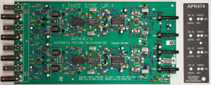
2. The second source of picture quality and the most common limitation is the frequency response of the transmission medium being used to convey the picture from the camera to the viewing location. When the picture is being sent by way of a Coaxial Cable or Unshielded Twisted Pair (UTP) cable, the loss in detail is a linear function of the distance that the cable must traverse and the intrinsic loss incurred by the composition of the cable. It is possible to compensate for this loss, effectively creating a zero loss cable path by automatically compensating for the loss of the coaxial cable. An amplifier with high frequency compensation designed to cancel the cable loss can be installed at the receiving end of the system. One such amplifier is the APR474 Automatic Picture Rejuvenator, which is able to compensate for cable loss up to 3,000 feet of RG59/U cable automatically.
Fiber Optic or Microwave transmission equipment can also transmit a picture up to their maximum distances, but in general, they are much more expensive than direct CCTV cable using the automatic cable equalizing system, APR474 Automatic Picture Rejuvenator cable equalizer. Fiber Optic transmission systems always use an AGC system that “clamps” a picture at the peak of white, instead of at black level, which is standard for video. This condition prevents a “fade to black”, which in turn reduces the dynamic range of the video picture giving you fewer levels of grey to black. Also any increase in the input luminance level by the camera “IRIS” will cause the lower negative portion of the video waveform and the SYNC pulse to be compressed below the normal level, which can result in picture rolling and other visible picture abnormalities at the DVR.
The DVR is also sensitive the under and over levels of video which will result in no picture being displayed at the output of the DVR during certain picture conditions. A normal cable installation using the APR474 will solve the cable distance and picture quality problem without the need for expensive Fiber Optic equipment.
3. Almost all CCTV systems use a video recording device either analog “VCR” or digital “DVR” to record the images from the cameras. With an analog VCR the picture detail is limited by the band-width of the input amplifiers and the ability of the tape heads to lay down and pick up the information from the magnetic tape.
With the digital “DVR” the picture information can be reduced by the input amplifiers, but the main cause of the picture quality issue is usually the amount of compression used on the incoming video. Video has a real-time image changing 60 times per second. The DVR will reduce the number of frames it receives in order to reduce the amount of data storage needed. The manufacture will also limit the video band-width in order to reduce the storage space as well. This reduction of band-width directly affects visible picture quality and is never specified by the manufacture of the DVRs. To test this on your DVR just look at the live picture on your monitor then play the recording back on the same monitor. The picture should be the same if it is not then you are seeing the effects of DVR compression and band-width reduction.
4. The forth factor is the Monitors ability to display high resolution pictures. This is set by the maximum number of pixels on the LCD or Plasma display and for the older CRT type monitors it is set by the frequency response of the input circuitry and in some cases the number of holes in the phosphor screen.
Obviously, it does no good to have one or more parts of the system capable of substantially greater detail than the rest of the system. Once the Camera, DVR, and Monitor are chosen, the greatest control of the picture quality that can be exercised is by connecting the APR474 Automatic Picture Rejuvenator to the receiving end of the cable. Applying an APR474 to the receiving end of the cable automatically cancels all the losses incurred by the cable, so that there is no loss of any kind remaining in the transmission path. The picture will have the same quality that could be seen on a test bench using the selected Camera, Recorder, and Monitor with zero feet of cable connected between them, no matter how long the actual Coaxial or UTP cables really are.
The frequency response diagram below graphically shows the quality advantage obtained when an APR474 is connected to the receiving end of a CCTV system of any length up to 5,000 feet. The graph plots the feet of cable traversed against the detail remaining in the picture at each distance covered. Notice that even 100 feet of cable will result in the loss of as much as 10% of the detail present at the camera output, which is even more than the loss of a coaxial cable equipped with an APR474 alter traversing 5,000 feet of the coaxial cable. Also the graph depicts the cable loss to be 50% when the picture has traveled over about 600 feet of cable without an APR474 connected. The APR474 will deliver a picture at 100% of the quality level that the Camera, Recorder, and Monitor are capable of producing.
The cable loss alone, for high definition Cameras, Recorders, and Monitors is higher than shown on the graph for any number of feet traversed., however the corrected overall frequency response, including the correction factor applied by the APR474 is not in any way affected by the extra loss induced by the cable at the higher frequencies being transmitted by the higher definition cameras. This means that the APR474 will correct the frequency response of cables transmitting medium definition signals or high definition signals without adjustment of any kind being required from the system operator. In every case whether high definition or medium definition pictures are being transmitted, the picture delivered to the receiving location will be the best that the Camera, Recorder, and Monitor can display. The APR474 Automatic Picture Rejuvenator was developed and is manufactured in the United States by FM Systems, Inc., and can be obtained by calling 1-800-235-6960 to place your order.


